Starting from the power supply article on raspyfi.com (raspyfi.com/the-best-raspber … er-supply/), I designed and built my own power supply unit using the LT3080 regulator. The key feature is that it provides two independent 5.0V power rails, one for the Raspberry Pi, and one for the audio interface. This helps minimize the voltage fluxuation interference between them.
It sounds very good altogether, though I haven’t done a lot of careful listening yet. I am quite excited over the amount of killer hi-fi that can be packed into an inexpensive Volumio-powered rig.
Your Blog is great a New Year’s present for all Volumio fans. I especially like your discussion about the “Enemies”. I also like your approach to having two rails.
I don’t have a scope, so I can’t verify the quality of the power rail but in the final version I want to use a regular transformer (7.5-9V) with a bridge rectifier and adequate capacitance. This could also be easily added to your circuit and your capacitance would then be part of the rectifier section.
In my setup I don’t seem to suffer from the voltage ramp-up during switch-on (the system seems to be stable from the start) because I don’t use a lot of capacitance but this would be introduced in the final version, so your warning comes right in time. For now I must probably also have ripple and, as a consequence, jitter.
In the system I envision I would not like to have the double switches you describe. I understand why you add them, but is there some way this could be avoided? Perhaps using a timing circuit and relays? Would the problem be somewhat mitigated by using a 12V input power?
Thanks for the kind words. Also, thanks for the link to the MagPi article. I am still learning and it is good to understand this kind of thing from different angles.
My electronics design skills and knowlege is far from professional, but while building mine, I did have the thought of designing in something for having the voltage turn on automatically once 5.0v is reached. I believe to do that properly, you would have to put a in a Zener diode across the output that would break at someplace below, but close to, 5.0 volts. The reverse current through the zener could then trigger a relay switch that would close the load circuit. For audio applications, I think it must be a physical relay to close the circuit. This is because transistor-based switching would have a slight voltage drop between the collector and emitter which would be a function of load current.
I did not think of some sort of timed switch. If that were possible and easy, that would be cool to add.
The first attempt I took was also using a transformer, but the one I had was 12V, and that would imply a rather large voltage drop causing some heat (12V * sqrt(2) == 17.37V once the capacitors are charged up, which means ~12 volts drop to 5V). I think for the Pi, one shoulld be designing for at least 500mA of current, so that means about 6 watts of heat to dissipate (P = Vdrop * I).
The other thing that I found uncomfortable about using a transformer and bridge rectifier to make DC from wall AC was that I don’t have a good grasp on the math for determining what the ripple current would actually be with a particular load. To be certain, one would probably need to do a circuit simulation. I started to poke around this LTSPICE tool linear.com/designtools/software/, but about three minutes in, I chickened out up and bought the 7.5V DC wall adapter.
I should mention another non-DIY solution I have heard of (and listened to) this AQVOX supply powering a Stello U3 (XMOS-based USB-to-S/PDIF unit) being driven from a MacBook in a hi-fi setup:
Apparently they use a very low noise regulator chip. The cost seems to be in the same ballpark as yours now that they have a double PSU rather than a quadruple one.
The linked unit seems to be 12 or 15V as configured by the switch. This is not going to do to power a USB bus, which is 5V. You are going to want to get this one:
Glancing into the datasheet on the TI TPS7A4700, it appears to be roughly equivalent to the LT3080 that I used. I would guess one brand is pretty much as good as any other for this type of part. I like that this kit has a credible heat sink setup to go on top of the flat surface of the regulator - definitely a lot nicer than what I have going on.
Since the unit takes AC as input, the advertized 88dB of ripple rejection on the first page of the TI datasheet needs to be taken different than in my design. Since I am starting with a DC input that has already been created by the off-the-shelf supply, it is going to only have a small bit of ripple to begin with. This is presumably less than the the ripple of the rectified AC coming off the 5600uF capacitor.
The other thing worth observing is that there is only a small capacitor of a size I can’t discern from the pictures. The datasheet for the TI part mentions 47uF as ‘highly reccomended’ on the output. but 10uF is the minumum. For the Raspberry Pi, there is the C6 capacitor (elinux.org/RPi_Hardware#Capacitor_C6) on its microUSB power input that serves the same purpose at 220uF. Most of the low-cost USB interfaces don’t appear to have a similarly large capacitor, but might not really have the same requirements as the Raspberry Pi, so it could be not worth worrying about.
Understood. One would have to compare costs as well. In your case one could add an unregulated linear DIY power supply to the circuit.
Since I am starting with a DC input that has already been created by the off-the-shelf supply, it is going to only have a small bit of ripple to begin with. This is presumably less than the the ripple of the rectified AC coming off the 5600uF capacitor.
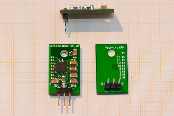
Want to share some details about my design. I like an idea to make small PCB with TI TPS7A4700 to replace standard voltage regulators, like 7805 (TO220), but don’t like existing solution (search on ebay for “ultra low noise ldo”)
I have designed new PCB with some improvement
Single side layout, all routes on top of the PCB. Back side is copper pour
15x25mm design
Universal - can set any voltage from 1.4 to 20.5V with 0.1v step (need to solder pins)
Can replace vertically or horizontally mounted TO220 (need to fix straight or angled header - can see on picture)
10uf input capacitor, 5 x 10uf output on PCB, all capacitors are Murata 25V X7R, means can use upto 25V DC IN
Below picture for my dual output power supply (very compact - 90x50x40mm)
What a nice work! Love the pin settings in the back! Altough I don’t know about TPS7A4700 I experimented as well with alternative voltage regulators (don’t like them to be so unefficient) . I did some experiments with LT3080 raspyfi.com/the-best-raspber … er-supply/
I would be really interested in trying yours, what are your plans about it?
If you are interested in learning exactly how to generate power and reduce your bill then this is the perfect resource for you! With the ever increasing costs of living, there is no better time than right now to stop throwing money out the window and start generating our own electricity. Check inplix.com and learn more about it.
Hi Jarred,
We would like to mention a project in this forum with a similar intend. https://volumio.org/forum/mdxs-the-source-everything-t3643.html
We also have a little site with some finding on regulators https://sites.google.com/a/architekturkonsulat.at/mdxs/regs.
We would recommend to get rid of the switching power supply in the front of your chain - why starting with lots of noise to be filtered out later?
We don’t like the sound of the TPS7A4700 (our ears are the only measuring tools we use). We liked the chip in the beginning because of it’s logic output setting but it’s way to expensive for it’s sound quality.
The power supply for the analog section of the DAC is of most importance. On the Hifiberry or IQaudIO boards just separate the 3V3 (DACs digital section) and the 5V (DACs analog section - there is an onboard reg to bring that down to 3V3) on the GPIOs. We won’t settle on the analog section for anything less that the SuperTeddyReg http://www.teddypardo.com/diy.html.
What we will try next is to actually get rid of the onboard 5V to 3V3 LDO of the DAC and connect a 3V3 SuperTeddyReg directly to the 3V3 AVDD of the PCM5122 chip.
Sorry for the mess - this is only an “evaluation” board.
Can you share some details about TPS7A4700 tests?
DC or AC Input? Input voltage? Did you test DIYINHK board or other? Have you try TI evaluation module?
We did try booth, DIYINHK and the TI module with a better PSU. We only listen (4x2 ears). We thinks it sound little bit flat. We like the timing/impulse of the LM317 but especially everything that the SuperTeddyReg delivers.
This was our first prototype with four DIYINHK TPS7A4700 (without their bridge rectifier, input at about 7V DC from 80VA toroidal) serving CPU, USB, DAC digit (3V3). & DAC analog section:
I am bit tired about PSU wiring and recently designed mezzanine power board, can be connected between PI and ANY HAT module to provide very clean power for both Pi and HAT.